Tritrix HT Build with Ceiling Bracket Design

Collapse
X
 
  • Time
  • Show
Clear All
new posts
  • Soundslike
    Seasoned Veteran
    • Feb 2010
    • 1080

    Tritrix HT Build with Ceiling Bracket Design

    This will be my first build post, though I've put together a set of Tritrix MTM TLs before this somewhat ambitious build. The goal was to build a home theater setup for my daughter, and a two channel stereo setup for my son, and their families of course. The HT setup will also include a subwoofer, that I was able to design with help from the experts on this board. The front two channels will utilize the transmission line variant, and the center and surrounds will utilize the vented version. I will make the cabinets rather than use the knock-down kit offered. I should hasten to add that unless you enjoy woodworking and have access to basic powertools, you'll probably be better off buying the kit. It's not free, of course, and you'll have to pay shipping on the rather heavy components, but it's reasonably priced -- especially when you take into account the price of MDF (currently around $33 per sheet).

    I've completed everything, but I'd appreciate your comments nonetheless. I'll share my mistakes, and the lessons learned, in the hope that others can learn from the experience, as I did. As I write this, I'm aware that builders and designers far more knowledgeable than I will likely read what I say. To you, I'll apologize in advance for covering things that are to you, elementary. But, a primary goal here, is to provide something that will be of value to those with even less experience than I have with this fascinating pursuit. I doubt that many experienced builders will find what I have to say all that enlightening, but there might be a few things of value. Regular participants will hardly find another Tritrix build thread compelling reading, but some may find the ceiling bracket design used for the rear surrounds interesting.

    I selected the Tritrix design for this project for several reasons. First, the Tritrix design has been highly acclaimed as an excellent high-value choice by those who should know. I am a strong believer in the advice so often seen here, that an inexperienced builder or would-be designer, will likely achieve much better results by using a proven design. Second, I'm very pleased with the first set I made. Third, the Tritrix kit offered by PE is a great value -- the discounted kit, as compared to purchasing individual parts, makes the Tritrix a very attractive option. Thank you Curt and Wayne...

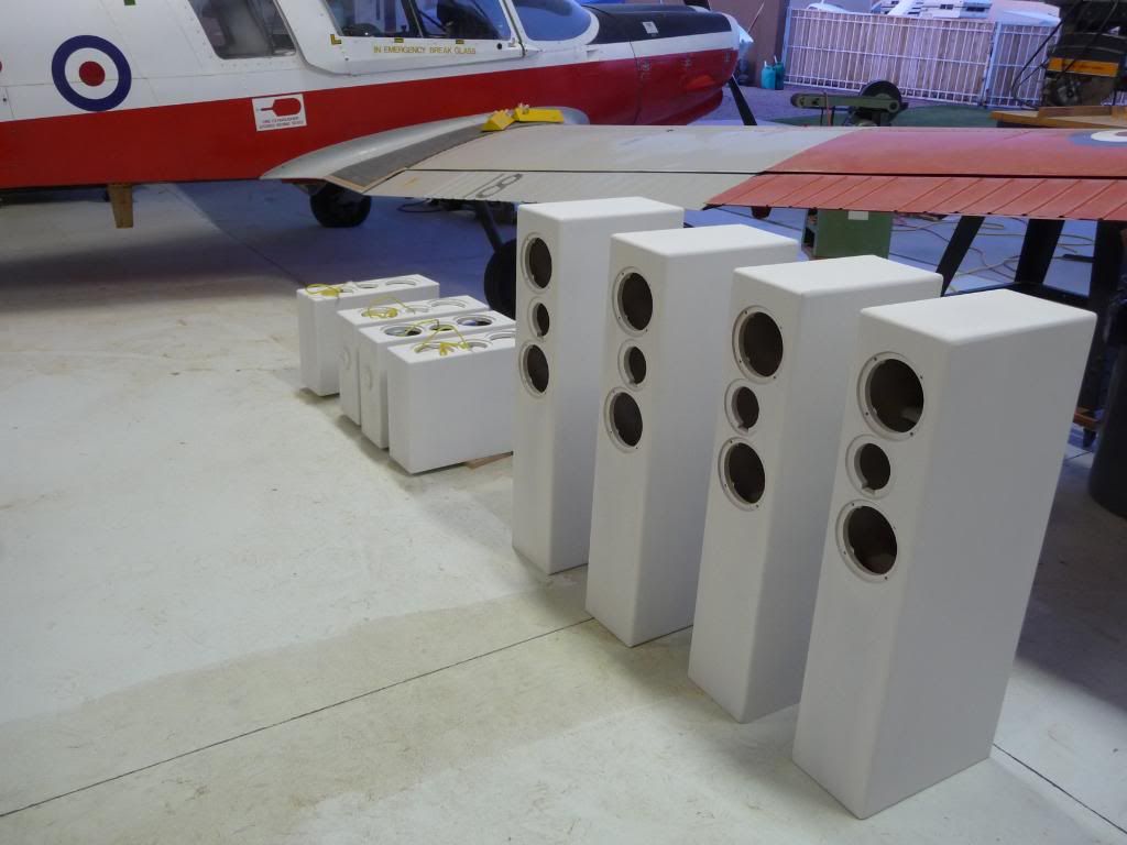
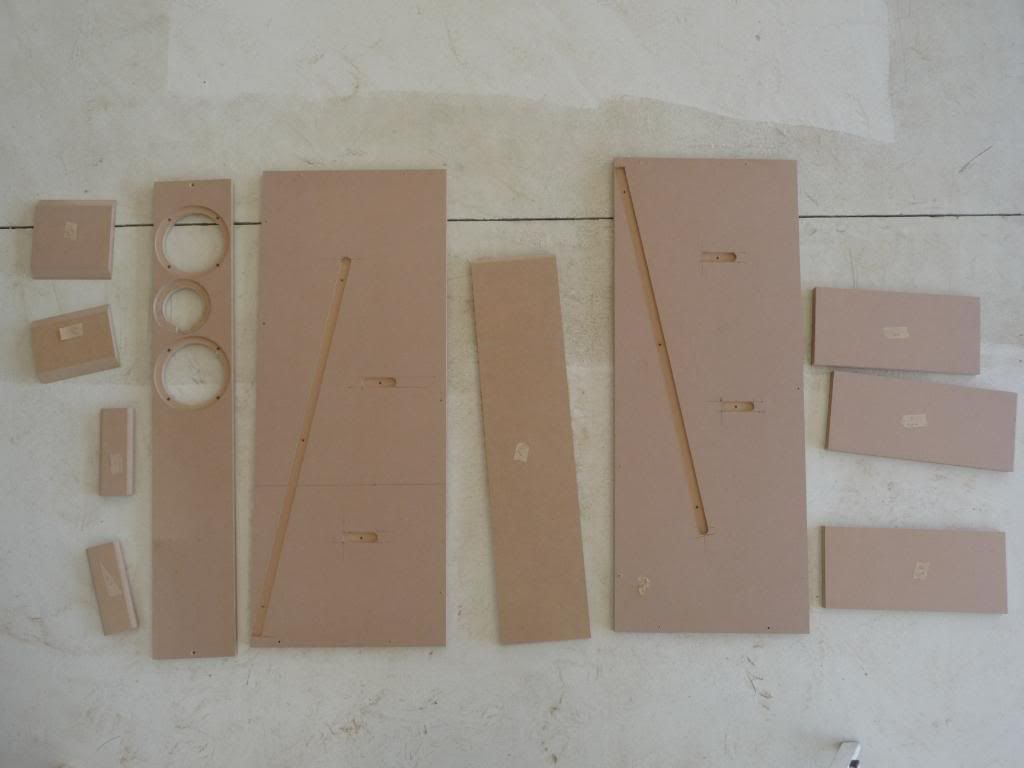
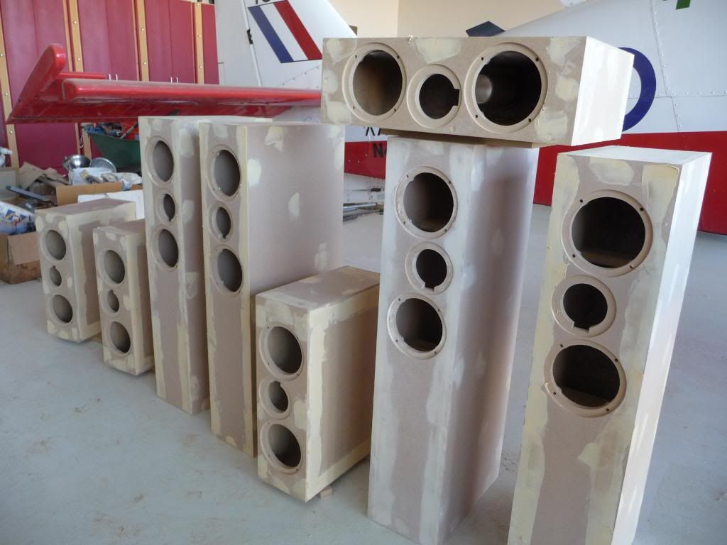
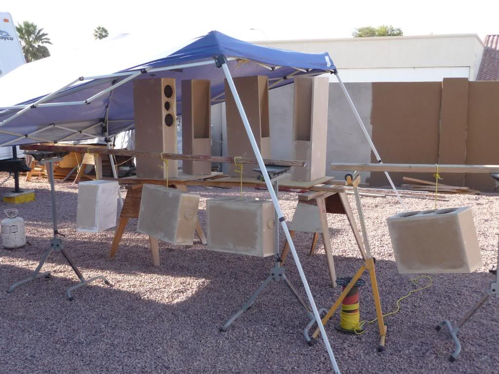
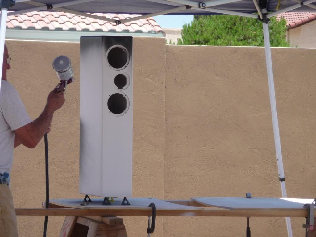
    I think it's probably a good idea to include a photo showing where this thread is headed. Because the Tritrix design is so common, I didn't bother to photograph the finished TLs -- they're visible in the background of some photos I will include, but until my daughter sends me a photo of the installed system, these will have to suffice. This is a photo of the completed enclosures in primer:


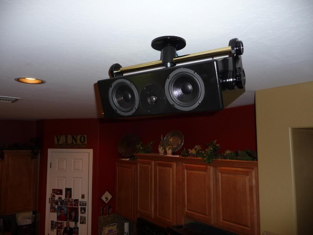
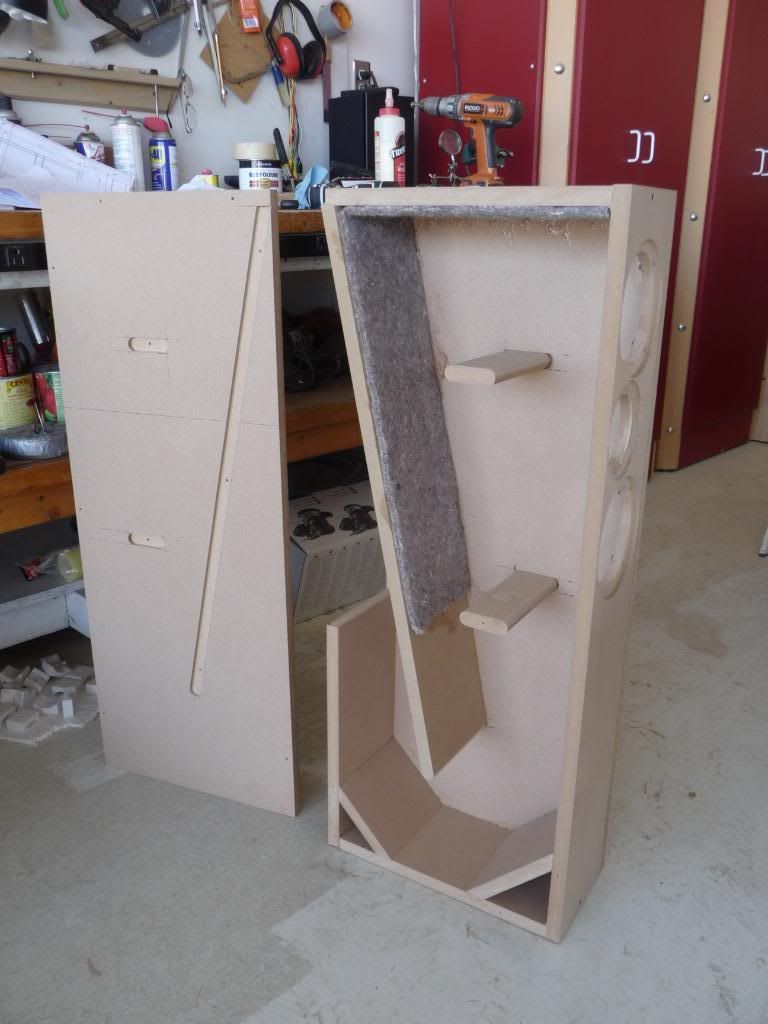
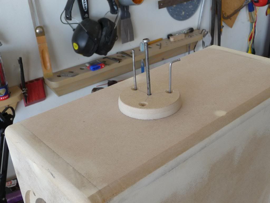
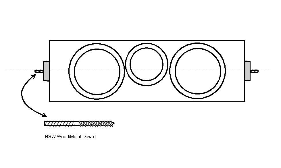
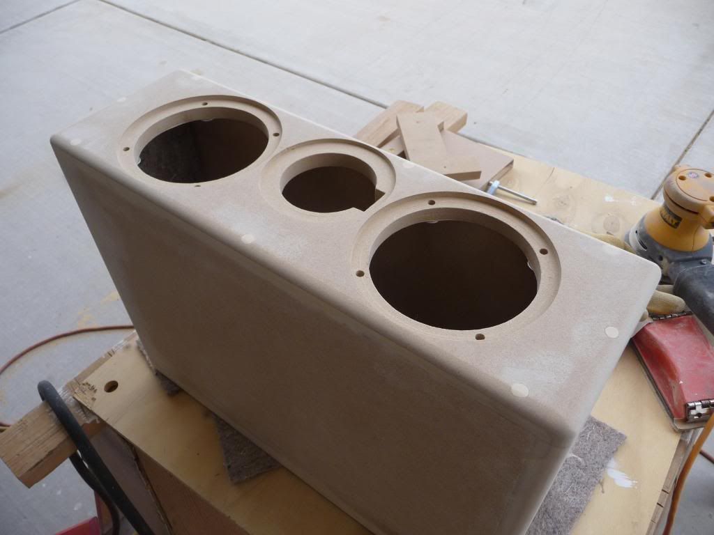
    This photo shows a surround with the bracket I'll describe later in this thread:


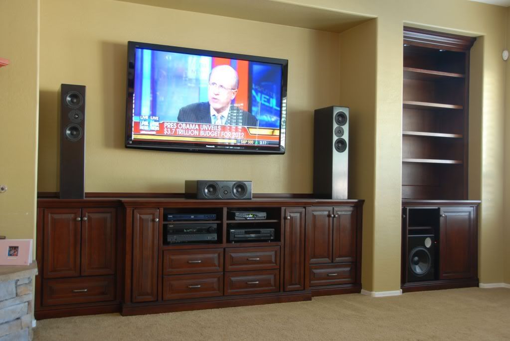
    Here's how the system looks in place in my daughter's home. Note the subwoofer tucked away in the cabinet on the right side.


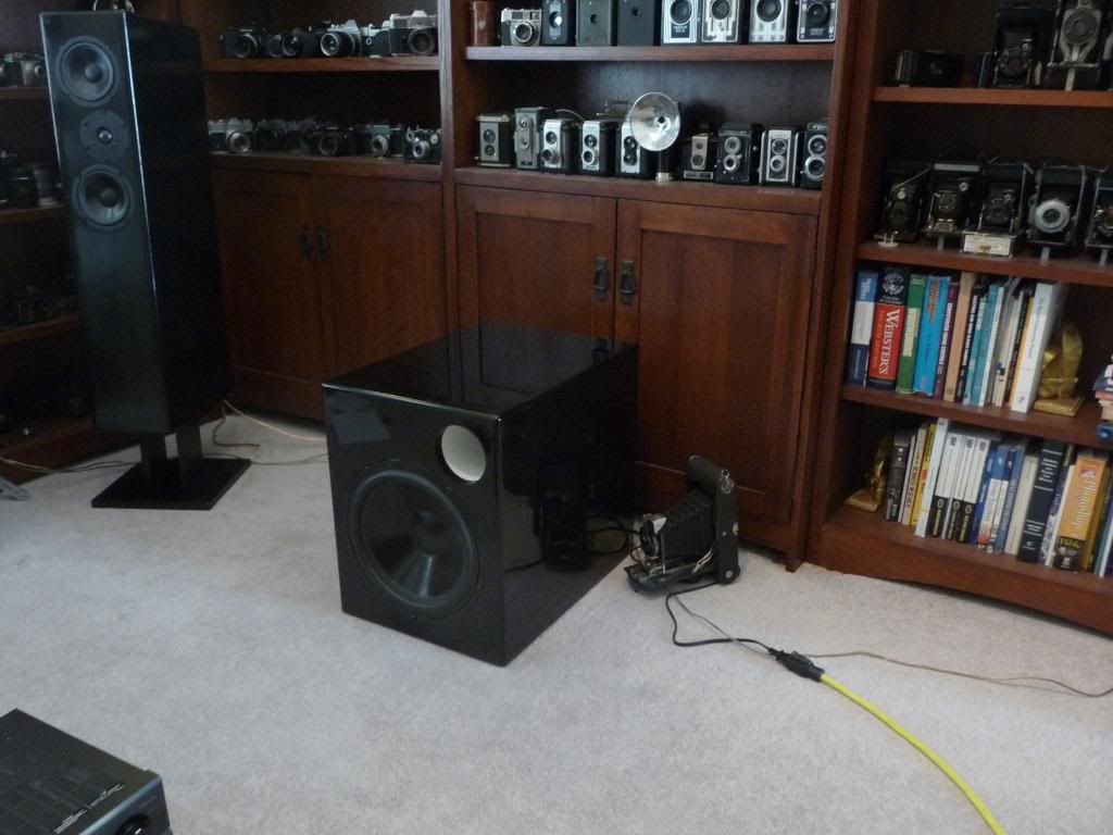
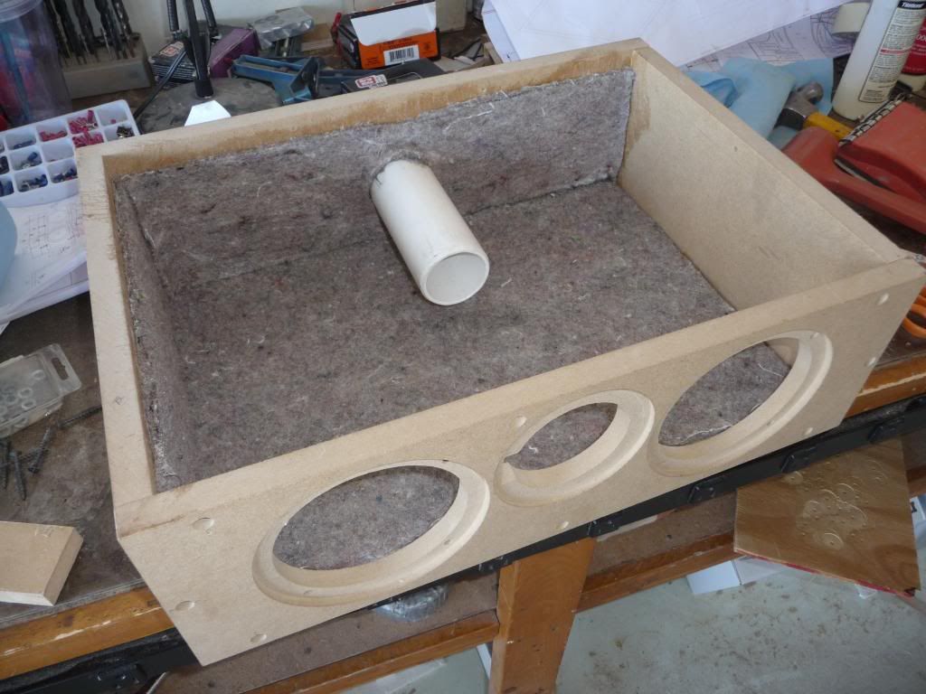
    And this would be a closer view of the subwoofer:


    I'll be back with more, hopefully this will be useful information for some...
    Last edited by Soundslike; 02-15-2011, 12:55 PM. Reason: updated link to sub
    Tritrix HT:http://techtalk.parts-express.com/sh...d.php?t=222519
    Dayton 12" Subwoofer: http://techtalk.parts-express.com/sh...d.php?t=222930
    Overnight Sensations: http://techtalk.parts-express.com/sh...d.php?t=223751
    Cerberus sub: http://techtalk.parts-express.com/sh...hlight=cerebus
    Duellatis: http://techtalk.parts-express.com/sh...d.php?t=224943
    NTN's: http://techtalk.parts-express.com/sh...d.php?t=227902
  • jared
    Been Around Awhile
    • Jul 2006
    • 89

    #2
    Re: Tritrix HT Build with Ceiling Bracket Design

    Looking great! I like the gloss finish and can appreciate the work it takes to get it to that point. Is that the Quattro 15 for the sub?

    Comment

    • Soundslike
      Seasoned Veteran
      • Feb 2010
      • 1080

      #3
      Re: Tritrix HT Build with Ceiling Bracket Design

      I elected to make my own enclosures with materials purchased from a local Home Depot, or maybe it was Lowes. I purchased three sheets of 3/4" (19mm) Medium-Density-Fibreboard (MDF) and then cut them into manageable pieces about 1/4" larger than the required width with a circular saw. MDF produces a huge amount of dust which pretty much gets everywhere, and wouldn't you know it, it's probably not too good for you.


      Many woodworkers recommend using a guide you can make yourself, when cutting large sheets of material.

      You'll find the guide to be very much worth the trouble if you cut sheets now and then, or if you have to make finish cuts with a circular saw.

      The pieces were cut to width using a table saw. A table saw will produce an accurate cut if the workpiece is supported adequately. If you don't have access to a table saw, you can cut accurately with the panel guide mentioned above. Pieces that overlap slightly can be cut flush later in the build process with a flush bit and a router, if you have access to one of those.


      A radial-arm saw was used to make the cross cuts. Radial-arm saws were common in workshops, until the mitre-saw was invented. They still have the advantage of making longer cuts.


      I recommend laying out (drawing) the driver cutouts on the baffle before doing any cutting. It helps, if you've made a miscalculation, because you're apt to spot the problem early on. With this project, I have eight baffles to mark.

      I bought a circle guide for speaker building and I'm glad I did. You can make your own, but unless it's a pretty elaborate design, you'll end up measuring and remeasuring a lot more than you cut. Still, if you're only making one pair of speakers, you can save some money. The guide uses a pivot which fits into a center hole you drill during the layout process.


      Here's the first baffle with the outer drive holes cut. Someone recommended in a thread I read on this forum earlier, that they prefer not to cut completely through the baffle with the router, but instead leave a paper-thin amount of material holding the waste (the part you're cutting out) to the work-piece. The reason for not cutting through is because if you do, the center hole where the guide pivot point is inserted will move and you're likely to get a gouge in the baffle. If you look closely at the baffle, you'll see a thin bit of material that remained after I pushed the waste out by hand. It's also worth mentioning that the outer recessed portion where the driver frame will set, must be cut first. I also recommend drilling the holes for the driver screws before cutting the openings. Doing so will allow you to use a drill press, and it's much easier to layout the holes accurately. You will also be able to install T-nuts, or hurricane nuts, before the enclosure is put together.


      If you make a mistake, all is not necessarily lost. In the photo below, you'll notice a fair amount of a filler I mixed up, and spread around the opening. The filler was made by mixing sawdust, which you'll have no trouble finding if you're using MDF, and white glue. White glue has sufficient strength, and it's inexpensive. The resulting paste makes for a strong repair, and you can avoid throwing away that piece you put so much work into. I've used it for other purposes as well, but it's not ideal for some things I will describe later. This repair will take a few more applications to build up the material back to the point it should be. If you look through the opening, you'll see one of the cutout waste pieces with the thin material still attached that was left by not cutting all the way through.


      The next step is to cut a small slot in the tweeter cutouts to make room for the terminals. I made this template that fits into the cutout to mark the eight baffles I was making. I found it tedious drawing guidelines for the cut after the driver holes are cut, using the usual combination square, and not particularly accurate. The template was made from 1/4" hardboard.


      A coping saw works well for cutting the notch needed for tweeter terminal clearance. The resulting hole usually isn't very neat, so I hold back from the line and use a modified square file to tidy things up. The file is a cheap Harbor Freight type with a cross sectional area of about 1/2" X 1/2". I ground one side flat making it possible to file material on one surface only, in the corners. A word of caution: When test fitting the tweeter, don't force anything or you might find that you've knocked off one of the terminals. It's easy to do, I find...

      Here's a baffle with cutouts, and the notch.

      In the next photo, I've begun the process of routing the angled groove that locates the back panel that defines the shape of the transmission line (it looks like a tunnel to me). I don't really think a dado is necessary -- after all, a ****-joint would have been sufficient if we were making a sealed or vented enclosure. But hey; from what I could tell on the YouTube videos showing how to put together a Tritrix TL, the knock-down kit features a dado, so mine will too. But I honestly think a builder could skip the dado. It probably serves more than anything else, to properly locate the angled panel for kit makers. It would be easy to locate the dado with a CNC router.

      If you opt to make the dado with a router however, you'll definitely want to layout the position of the dado, and cross braces. Do it in pencil, because if you're like me, you'll being doing a bit of erasing. It can be confusing. I strongly recommend that builders draw the enclosure to scale before beginning, in order to plan how they will locate the angled panel and braces.

      Once everything is properly laid out, it is best to make a jig to guide the router. One could use nothing more than a straight edge, but you'll need something to establish start and stop points. I made the jig you see in the photo out of scrap MDF (plenty of that laying around). Notice that it's "C-shaped;" it's those end pieces that limit the router's travel at start and finish. If anyone needs the dimensions I used, drop me a PM and I'll send them, but you'll probably need to alter them if you're using a different router (mines a Porter Cable). It's worth mentioning, I guess, that a 3/4 inch dado bit is used, and that repetitive 1/8" cuts are made until the right depth is achieved.

      I chose to use wood screws to assemble my 14 speaker enclosures, up to this point. I'm not so sure I'll do it again for reasons I'll explain. I like wood screws for several reasons. The add considerable strength when simple ****-joints are used and they facilitate the assembly process. Many, many, enclosures have been built with glue only, but this entails a process whereby one piece is carefully glued to another, clamped, and then left to sit until the glue dries. After a time, usually the next day, clamps are removed and another piece is added. Sometimes more than one, but never more than a few -- it's just too difficult to control several pieces of wood made slippery by glue. Using screws, one can avoid that difficulty because the screws hold everything in place while another piece is added. But to do it right, the clearance holes (I'm referring to the larger holes that pass through the top piece to allow the screw to reach the piece being attached to) should be drilled in advance. During the process of assembly, everything is dry fitted first, one screw at a time. In other words, you hold two pieces together and drill a pilot hole for the first screw, then insert the screw, realign everything then drill another pilot hole,insert another screw etc., repeating this procedure until the assembly is completed. Then things are disassembled piece by piece, wood chips blown away, glue added, and reassembled. That makes for an accurate assembly which can continue until the enclosure is completed. I'll have to continue in another post -- this one has exceeded the limit. Brevity has never been by strong suit...

      Tritrix HT:http://techtalk.parts-express.com/sh...d.php?t=222519
      Dayton 12" Subwoofer: http://techtalk.parts-express.com/sh...d.php?t=222930
      Overnight Sensations: http://techtalk.parts-express.com/sh...d.php?t=223751
      Cerberus sub: http://techtalk.parts-express.com/sh...hlight=cerebus
      Duellatis: http://techtalk.parts-express.com/sh...d.php?t=224943
      NTN's: http://techtalk.parts-express.com/sh...d.php?t=227902

      Comment

      • Soundslike
        Seasoned Veteran
        • Feb 2010
        • 1080

        #4
        Re: Tritrix HT Build with Ceiling Bracket Design

        Originally posted by jared
        Looking great! I like the gloss finish and can appreciate the work it takes to get it to that point. Is that the Quattro 15 for the sub?
        In keeping with the goal of high-value, and and not being at all certain I could produce a speaker that would be worth the effort even with expensive drivers, I opted for the Dayton SD315-88, 12" shielded DVC. Now that PE is reducing their line of shielded drivers, it's no longer available. It's also powered by a Dayton product, the SA-100 plate amp. I'll be getting to my finishing trials and tribulations later in the thread. Thanks for the compliment...
        Tritrix HT:http://techtalk.parts-express.com/sh...d.php?t=222519
        Dayton 12" Subwoofer: http://techtalk.parts-express.com/sh...d.php?t=222930
        Overnight Sensations: http://techtalk.parts-express.com/sh...d.php?t=223751
        Cerberus sub: http://techtalk.parts-express.com/sh...hlight=cerebus
        Duellatis: http://techtalk.parts-express.com/sh...d.php?t=224943
        NTN's: http://techtalk.parts-express.com/sh...d.php?t=227902

        Comment

        • Soundslike
          Seasoned Veteran
          • Feb 2010
          • 1080

          #5
          Re: Tritrix HT Build with Ceiling Bracket Design

          But, using screws causes problems during the finishing process. If rounded or angled edges are used, the screws must be countersunk well below the surface, but not so far as to compromise strength. If they're not deep enough, you'll hit them during the routing process -- pretty sparks result, but it's tough on bits, and you've got a defect you'll want to hide during the finishing process. Also, the countersunk screws leave holes that must be filled, and not just any filler is suitable. You'll need something tough that won't come out later on. I used the white glue/saw dust mixture described earlier, but it shrinks and must be reapplied. It's also difficult to sand flush so you end up with a less than perfect finish. So, next time I'll be dragging out the biscuit joiner -- that should keep thing aligned during assembly and add sufficient strength.

          I think it's a good idea to insert the hurricane or T-nuts, whichever you use, before the enclosures are assembled. If the holes are sized correctly, a press fit will be all that's needed. Glue can be used if you've oversized the holes, but there is a risk that the threads will be fouled -- that might necessitate using a thread-chaser or a tap to clean the threads. I measure the barrel with calipers to make sure I find the correct drill size.


          In the next photo, I arrayed the component parts necessary for one Tritrix TL enclosure


          This photo shows one nearly assembled TL enclosure. I used automotive carpet padding, a compressed fabric/fiber material on the top and behind the drivers. I don't know that I can recommend this material, some may find fault with it, but it seems to do the job fine in this application. I haven't experienced any problems, but then again, I don't have the critical ears that might detect an audible deficiency, if there is one. I'd be interested in what others have to say. I prefer to completely assemble the enclosure before installing the drivers or crossovers. That avoids the possibility of damage, whether physical or by paints and solvents.


          The next photo shows the interior of a vented enclosure that will be used either as a center, or as a surround. Note the use of PVC pipe for the vent -- it's epoxied in a hole cut with a Forsner bit and a drill press. You'll also note the use of automotive carpet padding on thee sides in the enclosure. The padding is secured to the panels with spray on contact adhesive. Look at all of those screw holes that will have to be filled.

          Tritrix HT:http://techtalk.parts-express.com/sh...d.php?t=222519
          Dayton 12" Subwoofer: http://techtalk.parts-express.com/sh...d.php?t=222930
          Overnight Sensations: http://techtalk.parts-express.com/sh...d.php?t=223751
          Cerberus sub: http://techtalk.parts-express.com/sh...hlight=cerebus
          Duellatis: http://techtalk.parts-express.com/sh...d.php?t=224943
          NTN's: http://techtalk.parts-express.com/sh...d.php?t=227902

          Comment

          • greywarden
            Seasoned Veteran
            • Sep 2010
            • 4434

            #6
            Re: Tritrix HT Build with Ceiling Bracket Design

            Awesome write-up, good job on the speakers too.

            रेतुर्न तो थे स्रोत
            return to the source
            leviathan system thread
            deadhorse thread
            shockwave build thread

            instagram :: greywarden_13

            in war, victory . . . in peace, vigilance . . . in death, sacrifice.

            Comment

            • Soundslike
              Seasoned Veteran
              • Feb 2010
              • 1080

              #7
              Re: Tritrix HT Build with Ceiling Bracket Design

              Originally posted by greywarden
              Awesome write-up, good job on the speakers too.
              Thanks for the encouragement -- I'm so happy you replied. While I was writing about the difficulties that follow in the finishing process, I remembered the quotation you use:

              Originally Posted by skyline_123 @ audioholics
              "In other words, one leaves you with hours worth of filling, sanding, refilling and resanding as well as the urge to quit life. The other way leaves you pure smoothness and a general desire to do something for charity. Next time, I choose smoothness and charity."

              That pretty well sums it up...
              Tritrix HT:http://techtalk.parts-express.com/sh...d.php?t=222519
              Dayton 12" Subwoofer: http://techtalk.parts-express.com/sh...d.php?t=222930
              Overnight Sensations: http://techtalk.parts-express.com/sh...d.php?t=223751
              Cerberus sub: http://techtalk.parts-express.com/sh...hlight=cerebus
              Duellatis: http://techtalk.parts-express.com/sh...d.php?t=224943
              NTN's: http://techtalk.parts-express.com/sh...d.php?t=227902

              Comment

              • Soundslike
                Seasoned Veteran
                • Feb 2010
                • 1080

                #8
                Re: Tritrix HT Build with Ceiling Bracket Design

                In this next photo, the build has progressed through the usual filling, sanding, more filling, resanding, and rounding over, I’m adding a disc-shaped pad that will be one of two pivot points used on this, and another speaker, that are to be suspended from a ceiling as surrounds.


                In this post, I’d like to address several points.

                1. Approaches to making a ceiling bracket
                2. Importance of balance in an adjustable mount
                3. Locating and orienting the pads
                4. Making MDF discs

                First, take a look at the following drawing for a clearer idea of what I’m trying to accomplish in the photo.


                Looking at speaker brackets in general, I suppose they could be grouped into two categories – those that can be adjusted and those that can’t. If an arrangement whereby a speaker is permanently aimed can be accepted, then mounting is much simpler because all that is required is rigid mounts. But if the speaker is to be infinitely adjustable, or nearly so, then it must be mounted with a swivel point around a vertical and a horizontal axis.

                Movement around a horizontal axis, as depicted by the centerline in the drawing, will require that the speaker attach points be near the center of gravity. The closer the better, because if it is out of balance, it will have a natural tendency to move in the direction that gravity commands. Either the front or the back of the speaker will want to move towards the floor. Some imbalance can be tolerated, but a tighter connection at the pivot point will be required. Imbalance will also tend to push a center column out of plumb, i.e., gravity will exert a force that makes the column want to move out of vertical alignment.

                To find the center of gravity, I loaded up a finished enclosure with drivers and crossover components, placed as nearly as possible to the location where they would be permanently mounted. I then placed the enclosure on a fulcrum and experimented until I found the location where it seemed most balanced. From that point, I measured up halfway on the enclosure’s side and marked a point. I transferred the point to the other side by measuring. That approach ignores the vertical location of weight or mass, but you can come fairly close.

                I decided that a better look could be achieved by using three brass plated screws, countersunk, but exposed, arranged around the pad. That necessitates finding three different angles within the circle that designates the outline of the pad, and for appearance sake one should be oriented to the vertical. The second and third screws are located at 120 and 240 degrees. The reason I mention all of this is to encourage builders to lay-out all of these locations on the work piece before the pad is cut. It’s far easier to do while you still have straight edges for reference lines. It’s probably also a good idea to drill all necessary holes before the piece is cut.

                You will notice, as this thread progresses, that a lot of discs fashioned out of MDF are used to fabricate a mounting system for two speakers. The number, I believe, is about 28. In light of this, I thought a few suggestions about how to easily make them might be helpful.

                After determining the size, mark the piece, or pieces on a scrap piece of MDF. Most pieces will need a center hole, and the pads need holes for the screws. Cut the work piece out to rough shape and sand to final size using whatever tool you have. I get good results using a bench mounted disc sander like one of these sold by Harbor Freight, as shown here:

                Harbor Freight buys their top quality tools from the same factories that supply our competitors. We cut out the middleman and pass the savings to you!


                More on Harbor Freight later in the thread.

                Using the disk sander, lightly sand while rotating the piece. It’s important to more or less constantly rotate the piece in order to avoid flat spots. Gradually sneak up to the line, but try not to remove the full line, or you’ll lose your reference and likely will end up with a less accurate piece. If you want higher precision, you can make a jig, such as the one shown here:


                If you don’t have access to a disk sander, you can very likely find a jig plan on the Internet that will allow you to vertically mount whatever type of sander you have. Here are some examples using belt sanders (but if you have one of those, you probably don’t need any advice):


                I could swear that I’ve seen plans for a jig to mount an orbital sander vertically, but for the life of me, I can’t find it. That might be an option for someone who doesn’t have access to a belt or disc sander.
                Tritrix HT:http://techtalk.parts-express.com/sh...d.php?t=222519
                Dayton 12" Subwoofer: http://techtalk.parts-express.com/sh...d.php?t=222930
                Overnight Sensations: http://techtalk.parts-express.com/sh...d.php?t=223751
                Cerberus sub: http://techtalk.parts-express.com/sh...hlight=cerebus
                Duellatis: http://techtalk.parts-express.com/sh...d.php?t=224943
                NTN's: http://techtalk.parts-express.com/sh...d.php?t=227902

                Comment

                • Soundslike
                  Seasoned Veteran
                  • Feb 2010
                  • 1080

                  #9
                  Re: Tritrix HT Build with Ceiling Bracket Design

                  In the next photo, I've gotten all of the enclosures assembled, ready for sanding and rounding of the edges. To get to this point, I've filled all holes with a putty I mixed up consisting of white glue and sawdust. As I mentioned earlier, the putty is strong, but it does shrink somewhat, and it's not easy to sand. The ideal filler is one that is strong, never comes out, and sands easily, but I've yet to find it. So, following a couple applications of the aforementioned putty and coarse sanding with a random orbit sander, I've applied a water based wood filler. I wouldn't trust it not to come out of a divot the size of a screw hole, but it does sand easily and it feathers out nicely.


                  Here's a close view of a vented enclosure after final sanding, and the front, sides and top edges have been rounded with a 1/2" router round-over bit. The back edges are left square. A flexible sponge-like sanding block works well for smoothing out any tool marks left by the router. Notice how far the round over cuts into the screw countersink holes. Those filled screw holes are going to present a challenge later during the finishing process.


                  Here's the stuff I chose to finish the enclosures -- it came from a local paint store and was recommended by the sales guy who seemed to know what he was talking about. It turned out to be essentially the same stuff you can get your home center. It's not bad, but conditions have to be good if you are to get a good finish. There are better choices. MDF can thwart a lot of primer types. Water based types raise the grain, or more precisely, the little bits of compressed wood that makes up the material. MDF can also swell dramatically if it gets wet. The edges are most difficult to seal. In the past, I've had some success using a mixture of white glue and water but the grain does rise, and when you sand it, you knock off the tops of the high particles which makes them absorbent again. Knowing that old furniture makers used to seal their creations with a coat or two of shellac, I decided to try a shellac based primer. That caused a lot of problems -- it was impossible to get a smooth application in the summer heat, and I doubt it can ever work well without thinning, even in milder climates.

                  Tritrix HT:http://techtalk.parts-express.com/sh...d.php?t=222519
                  Dayton 12" Subwoofer: http://techtalk.parts-express.com/sh...d.php?t=222930
                  Overnight Sensations: http://techtalk.parts-express.com/sh...d.php?t=223751
                  Cerberus sub: http://techtalk.parts-express.com/sh...hlight=cerebus
                  Duellatis: http://techtalk.parts-express.com/sh...d.php?t=224943
                  NTN's: http://techtalk.parts-express.com/sh...d.php?t=227902

                  Comment

                  • Soundslike
                    Seasoned Veteran
                    • Feb 2010
                    • 1080

                    #10
                    Re: Tritrix HT Build with Ceiling Bracket Design

                    This next photo shows the setup I used for spray painting the enclosures. Naturally, I moved everything outside. It being summertime in Arizona, I thought shade would be a good idea. I erected an Easyup shade to avoid direct sun on the enclosures which I'm sure helped, but not enough. The best I could hope to achieve was whatever the outside temperature was, and as I recall, it was somewhere around 105 degrees.

                    The four vented enclosures were suspended by tying a rope around a short piece of 1X2, then inserting it inside the speaker enclosure, just behind the tweeter cutout.

                    I've had spray equipment for years, but for this project, I purchased an inexpensive gravity feed gun I have an old conventional Binks gun that works well, but the gravity feed type offers the advantage of higher efficiency -- more of the paint gets applied to the workpiece, as opposed to drifting away as overspray. When overspray drifts, I'm convinced it looks for the most expensive shiny thing it can find before settling, such as a Ferrari, Porche, or Mercedes. Airplanes are also favorite destinations. So, less overspray is an advantage, and using a gun with the paint cup on the top looks cool too.


                    This photo shows the enclosures with the shellac based primer applied. During summertime months in the greater Phoenix area, after about the 1st of July, we often get evening Thunderstorms and they’re always accompanied by blowing dust, and now and then, rain. That makes it unwise to leave anything outside overnight that can catch the wind, or isn’t waterproof. Since the enclosures failed both of those tests, I move them back inside. Everything looks great in primer, doesn't it....

                    But, if I had really close shot, you'd see that the primer left an orange-peel surface. This stuff covers well -- if you look at the product page on the Zinsser web site, it touts BIN primer for its superior sealing and hiding capability. But Zinsser doesn't make any claim of smooth flowing fine finishes. My mistake for not doing my research. There is one rule I would pass along to anyone who is striving for a good, high-quality, finish. Know the product you're using so you'll know what it's going to do in the application you're using it for. You can get a nice looking finish using the oil-based paints available in home improvement centers, but if you can find the time to experiment with the product before applying it to your project, you're well advised to do so.

                    Tritrix HT:http://techtalk.parts-express.com/sh...d.php?t=222519
                    Dayton 12" Subwoofer: http://techtalk.parts-express.com/sh...d.php?t=222930
                    Overnight Sensations: http://techtalk.parts-express.com/sh...d.php?t=223751
                    Cerberus sub: http://techtalk.parts-express.com/sh...hlight=cerebus
                    Duellatis: http://techtalk.parts-express.com/sh...d.php?t=224943
                    NTN's: http://techtalk.parts-express.com/sh...d.php?t=227902

                    Comment

                    • Soundslike
                      Seasoned Veteran
                      • Feb 2010
                      • 1080

                      #11
                      Re: Tritrix HT Build with Ceiling Bracket Design

                      Even though the prime coats were not as smooth as I liked, I decided to press on with the materials I had purchased for the project. When you build a batch of speakers, or anything else I guess, it's not easy to change direction. For one thing, the more of something you buy, the harder it is to abandon it, and replace it with something else. And usually, the process of sanding between coats produces dramatic improvement with succeeding coat. But MDF does resist the painter's efforts to produce a nice finish. It readily absorbs paint, particularly on the edges. The primer must seal the material, if you are to end up with a nice, shiny finish, free of defects. Any spot where you sand through the primer down to the MDF, will stand out as a dull spot. In the following photo, I'm spraying on black alkyd enamel with that inexpensive gravity feed gun I mentioned earlier. The gun worked surprisingly well and convinced me that getting a good one would be worthwhile.


                      In the next photo, I'm beginning the process of making the crossover networks. What happened to the obligatory photos of the enclosures painted in black you ask? Well, they turned out okay, but I wasn't happy and apparently I didn't have sufficient motivation to snap a picture. I'll include a photo or two later on in the thread, showing the completed speakers in what is now their natural environment. Cue the Jungle sounds, Marlon.

                      Note: Photo added at beginning of thread on 2/15/11

                      Back to the crossover networks. I planned the layout by creating a scale drawing showing placement of each component. The networks will utilize boards cut from 1/4" hardboard (often called by the brand name "Masonite"), with all connections made up on the underside of the board. I prefer to use terminal connectors, mainly I guess, for neatness sake. The drawing was made using a computer drafting program, which makes the task easier because you can drag things around, resize things, rotate things, and because the dimensions are calculated for you. I began by measuring all of the components and then drawing them to scale. I first placed the inductors in the drawing because I wanted them to be as far apart as possible on whatever size board I ended up with, and of course, one should be standing vertical, while the other is laid flat. Then I placed the other components, including the terminal connectors. A bit of trial and error produces a satisfactory layout which can then be "wired together" by drawing lines depicting where connections are made, etc. Then, the drawing is duplicated and flipped over to produce a mirror image that will serve as a kind of road map for making connections beneath the board.

                      That blue tint the photo has reminds me of those Viagra commercials on TV. Don't be confused -- you probably have to be over 45 or 50 to understand.
                      I wonder if that came from the art department or the law department?

                      Last edited by Soundslike; 02-15-2011, 12:59 PM.
                      Tritrix HT:http://techtalk.parts-express.com/sh...d.php?t=222519
                      Dayton 12" Subwoofer: http://techtalk.parts-express.com/sh...d.php?t=222930
                      Overnight Sensations: http://techtalk.parts-express.com/sh...d.php?t=223751
                      Cerberus sub: http://techtalk.parts-express.com/sh...hlight=cerebus
                      Duellatis: http://techtalk.parts-express.com/sh...d.php?t=224943
                      NTN's: http://techtalk.parts-express.com/sh...d.php?t=227902

                      Comment

                      • greywarden
                        Seasoned Veteran
                        • Sep 2010
                        • 4434

                        #12
                        Re: Tritrix HT Build with Ceiling Bracket Design

                        I'm interested in how your crossovers turned out, I have my parts, in waiting for payday to come around, so I can get started on them.

                        रेतुर्न तो थे स्रोत
                        return to the source
                        leviathan system thread
                        deadhorse thread
                        shockwave build thread

                        instagram :: greywarden_13

                        in war, victory . . . in peace, vigilance . . . in death, sacrifice.

                        Comment

                        • Soundslike
                          Seasoned Veteran
                          • Feb 2010
                          • 1080

                          #13
                          Re: Tritrix HT Build with Ceiling Bracket Design

                          Originally posted by greywarden
                          I'm interested in how your crossovers turned out, I have my parts, in waiting for payday to come around, so I can get started on them.
                          Thanks for the question -- here's more on the crossover networks (in the following posts).
                          Tritrix HT:http://techtalk.parts-express.com/sh...d.php?t=222519
                          Dayton 12" Subwoofer: http://techtalk.parts-express.com/sh...d.php?t=222930
                          Overnight Sensations: http://techtalk.parts-express.com/sh...d.php?t=223751
                          Cerberus sub: http://techtalk.parts-express.com/sh...hlight=cerebus
                          Duellatis: http://techtalk.parts-express.com/sh...d.php?t=224943
                          NTN's: http://techtalk.parts-express.com/sh...d.php?t=227902

                          Comment

                          • jcpahman77
                            Senior Member
                            • Aug 2010
                            • 932

                            #14
                            Re: Tritrix HT Build with Ceiling Bracket Design

                            Between the popularity of the TriTrix TL knock down kit and all the very well informed info here I'm wondering if it wouldn't be prudent to make this a sticky. I get the feeling the OP has quite a bit more up his sleeve yet for this thread and I can't help but think that even experienced speaker builders can benefit from the advice that is posted here.

                            Comment

                            • Soundslike
                              Seasoned Veteran
                              • Feb 2010
                              • 1080

                              #15
                              Re: Tritrix HT Build with Ceiling Bracket Design

                              Using the measurements produced in the CAD drawing, I made this template, again out of 1/4" hardboard. It's the same as the actual boards I will make for the eight crossover networks I need. In the photo, I'm in the process of transferring the holes (where the component leads will pass through the board) to another board. I placed the template over the identically sized board and carefully drilled the first hole in one of the corners. To anchor one corner, and improve accuracy, I inserted a pin through through both. Next, I placed the board edgewise on the workbench which aligned the board with the template, and drilled a second hole through which a second pin was inserted. The purpose of the second pin is to keep board and template in the correct position relative to each other while the rest of the holes are drilled.


                              In this photo, I'm drilling through the template into the board below. I'm only marking the board with the drill, making a small dimple in the board where each hole goes. The actual drilling process was done with a drill press, several boards clamped together in order to speed up the process. Obviously, it isn't absolutely necessary to use a drill press, but it does avoid the occasional errant hole drilled at an angle. By the way, the reason I used the drill to mark the hole locations is that other methods you see on the bench, such as the nail and hammer, or the scratch awl, bounced things around too much.
                              As you can see in the photo, I didn't bother sanding the edges of the boards considering it to be "uncraftsmanlike," because after all, they're going inside the enclosure where they won't be seen. I probably will next time, if only to avoid posting a photo showing, gasp, rough edges.


                              In this next photo, you see a finished crossover network, with leads attached to the terminals.

                              Tritrix HT:http://techtalk.parts-express.com/sh...d.php?t=222519
                              Dayton 12" Subwoofer: http://techtalk.parts-express.com/sh...d.php?t=222930
                              Overnight Sensations: http://techtalk.parts-express.com/sh...d.php?t=223751
                              Cerberus sub: http://techtalk.parts-express.com/sh...hlight=cerebus
                              Duellatis: http://techtalk.parts-express.com/sh...d.php?t=224943
                              NTN's: http://techtalk.parts-express.com/sh...d.php?t=227902

                              Comment

                              Working...