
 Tweet
Tweet
Here's another PCD question for ya, Jeff:
I'd like to use PCD to model the response of a system using an active crossover. Part of the crossover will be baffle step compensation - e.g. a shelving LP filter. How do you model that in PCD? I couldn't figure it out.
-Charlie
I'd like to use PCD to model the response of a system using an active crossover. Part of the crossover will be baffle step compensation - e.g. a shelving LP filter. How do you model that in PCD? I couldn't figure it out.
-Charlie
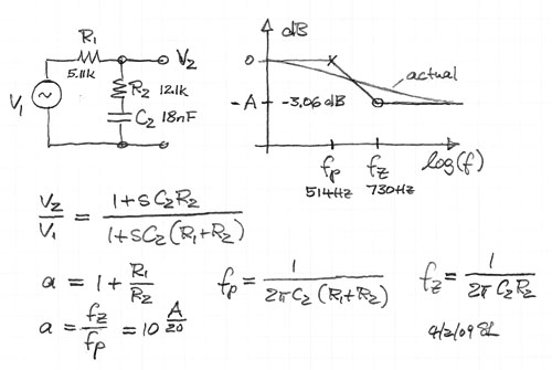


 I am NOT trying to tell you how to design your crossovers. I really only wanted to know how I could model a first order shelving filter in PCD's active circuit section, since I happen to like using it for baffle step compensation. Since you seem to have indicated that you can't model that in PCD, and that you aren't open to any more development with PCD, I think that is all that I need to know at this point.


Comment